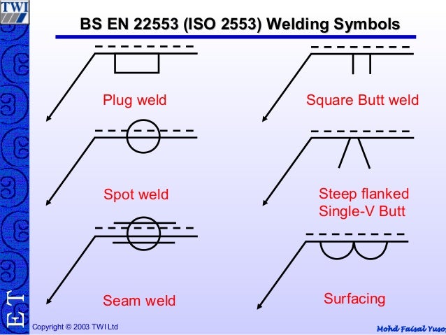
The symbols and conventions used in welding documentation are specified in national and international standards such as ISO 2553 Welded, brazed and soldered joints -- Symbolic representation on drawings and ISO 4063 Welding and allied processes -- Nomenclature of processes and reference numbers. The US standard symbols are outlined by the American National Standards Institute and the American Welding Society and are noted as 'ANSI/AWS'.[1] Due in part to the growth of the oil industry, this symbol set was used during the 1990s in about 50% of the world's welding operations.[1] An ISO committee sought to establish a global standard during this decade.[1]
In engineering drawings, each weld is conventionally identified by an arrow which points to the joint to be welded. The arrow is annotated with letters, numbers and symbols which indicate the exact specification of the weld. In complex applications, such as those involving alloys other than mild steel, more information may be called for than can comfortably be indicated using the symbols alone.[1] Annotations are used in these cases.[1]
The symbols and conventions used in welding documentation are specified in national and international standards such as ISO 2553 Welded, brazed and soldered joints -- Symbolic representation on drawings and ISO 4063 Welding and allied processes -- Nomenclature of processes and reference numbers. Created Date: 1/13/2012 8:35:12 AM. ISO Weld Symbol Question. Ali, The simple answer is no. Per the ISO Specification for welds, the dashed line is part of the change in the standard, therefore, it is not optional. You are in the same situation as my company is; we create drawings per ANSI using imperial units and we also create drawing per ISO using metric units. Our decision.
Component elements[edit]
In the US, the component elements of the weld specification are:[2]
- The reference line - the body of the arrow which is the baseline for the specification.
- The arrow tip which goes at an angle to the reference line, pointing to the joint to be welded.
- The tail which goes at the other end of the reference line.
- The basic welding symbol which goes on the reference line to indicate the shape of the weld such as a fillet or plug. The symbol is placed on the arrow side or other side of the line to indicate which side of the joint the weld goes.
- The dimensions and other numbers such as the length of the weld or number of spot welds go above and below the reference line.
- Supplementary symbols go at the junction of the reference line and the arrow tip. One such symbol is a circle to indicate an all-around weld, which goes on every side of the joint.
- Finish symbols go above the reference line to indicate the surface contour or finish of the weld such as flush, convex or concave.
- Letters indicating the welding process are placed at the tail end, such as AHW for atomic hydrogen welding. Further examples include:
Abbreviations for welding processes[edit]
If a particular welding process needs to be indicated in addition to the symbols, the following abbreviations are commonly used in North America:[3][2]
| Designation | Welding process |
|---|---|
| CAW | Carbon-arc welding |
| DB | Dip brazing |
| FB | Furnace brazing |
| FW | Flash welding |
| GMAW | Gas metal-arc welding |
| GTAW | Gas tungsten-arc welding |
| IB | Induction brazing |
| OAW | Oxy-acetylene welding |
| OHW | Oxy-hydrogen welding |
| PGW | Pressure gas welding |
| RB | Resistance brazing |
| SAW | Submerged arc welding |
| TB | Torch brazing |
| UW | Upset welding |
| SMAW | Shielded Metal Arc Welding |
References[edit]
- ^ abcdeE. N. Gregory; Ann A. Armstrong (20 April 2005). Welding symbols on drawings. CRC Press. pp. 7–8. ISBN978-0-8493-3591-4. Retrieved 10 October 2011.
- ^ abWelding Theory and Application(PDF) (Training Circular 9-237), Department of the Army, 7 May 1993
- ^'Welding Inspection Handbook', 3rd edition, American Welding Society, ISBN0-87171-560-0, Miami, FL, pp. 10-11 (2000)

Further reading[edit]
- K.L.Narayana,P.Kannaiah,K.Venkata Reddy (2008). Machine Drawing. New age International. ISBN978-81-224-1917-7.CS1 maint: Multiple names: authors list (link)
- N.D.Bhatt,V.M.Panchal (2003). Machine Drawing. Charotar Publishing House. ISBN81-85594-19-8.
External links[edit]
- Welding symbols at Arcraft Plasma Ltd.
- Welding symbols and definitions at Metallic Fusion
- Standard welding symbols at Engineer's Edge
- Extract from Chapter 26 – Welding and welding symbols in Manual of Engineering Drawing by Colin H. Simmons and Dennis E. Maguire. Newnes (2004). ISBN0-7506-5120-2

Iso Standard Weld Symbols
Iso Welding Symbols Explained
The weld type symbol is typically placed above or below the center of the reference line, depending on which side of the joint it's on. The symbol is interpreted as a simplified cross-section of the weld.
'Fillet welding refers to the process of joining two pieces of metal together whether they be perpendicular or at an angle. These welds are commonly referred to as Tee joints which are two pieces of metal perpendicular to each other or Lap joints which are two pieces of metal that overlap and are welded at the edges. The weld is aesthetically triangular in shape and may have a concave, flat or convex surface depending on the welder’s technique. Welders use fillet welds when connecting flanges to pipes, welding cross sections of infrastructure, and when fastening metal by bolts isn't strong enough.' [Fillet weld. Wikipedia]
The engineering drawing example Welding symbols is included in the Mechanical Engineering solution from Engineering area of ConceptDraw Solution Park.